Thinking in phase: from a one-sample delay to the Hilbert transform in FAUST
[ 2026-10-04 ]What happens to a signal when you add a copy of itself delayed by a single sample? Following that question step by step leads through FIR and feedback filters, poles and zeros, the comb, the allpass, and the difference between a delay in time and a delay in degrees, up to the Hilbert transform: two chains of allpass filters that let you shift every frequency by the same angle.
Conventions
- All examples use fs = 44100 Hz, so Nyquist = 22050 Hz.
- Faust notation:
x'is x delayed by 1 sample,x''by 2 samples. Inf ~ gthe signal fed back throughgarrives with a 1-sample delay. - “Phase delay” is measured in degrees and is positive when the output is late.
- Click on any figure to open it at full size.
1. Delay + sum: cancellation or reinforcement
1.1 Phase as a wheel
Before adding anything, it helps to picture a sinusoid as a point going round a wheel: one full cycle of the sinusoid is one full turn, 360°. At every sample the wheel turns by a fixed angle, which depends on the frequency:
angle per sample = 360° × f / fs
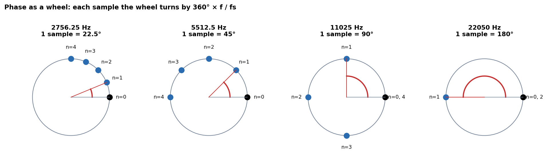
| f | one sample is… |
|---|---|
| 0 Hz | 0° (the wheel is still) |
| 2756 Hz | 22.5° |
| 5512 Hz | 45° |
| 11025 Hz (fs/4) | 90°: a quarter of a turn |
| 22050 Hz (fs/2) | 180°: half a turn, the signal alternates +1, −1, +1… |
So delaying by one sample means turning the wheel back by that angle. The same 1-sample delay is a tiny angle at low frequencies and a big one at high frequencies. Keep this in mind: it is the seed of everything in section 4.
1.2 Adding the delayed copy
Take a sinusoid as input and imagine sweeping its frequency. What happens if we delay it by one sample and add it to the original?
- At 22050 Hz the delayed copy is half a cycle (180°) late, i.e. upside down: perfect cancellation. Why? At 44100 samples per second a 22050 Hz sinusoid takes 2 samples to complete a cycle: one positive, one negative. Delayed by one sample, wherever the original is +1 the copy is −1. They are exactly in opposite phase.
- Going down in frequency the cancellation decreases gradually, but not in a straight line. It follows a cosine:
amplitude = 2·|cos(π·f/fs)|- at 11025 Hz a cycle lasts 4 samples, so 1 sample is a quarter cycle (90°): amplitude 1.41 (√2);
- at 5512 Hz a cycle lasts 8 samples, 1 sample = 45°: amplitude 1.85;
- at 2756 Hz a cycle lasts 16 samples, 1 sample = 22.5°: amplitude 1.96.
- At 0 Hz the two signals are perfectly in phase: reinforcement, amplitude 2.
Where does the cosine come from? On the wheel, x and x’ are two arrows of the same length, separated by the angle of one sample. Their sum is an arrow whose length depends on that angle: 2 when they point the same way (0°), 0 when they point in opposite directions (180°), √2 when they are at right angles (90°). In general it is 2·cos(angle/2). (Adding arrows on a wheel will come back in section 6.)
Sample by sample (the sum is in green, with its continuous curve):
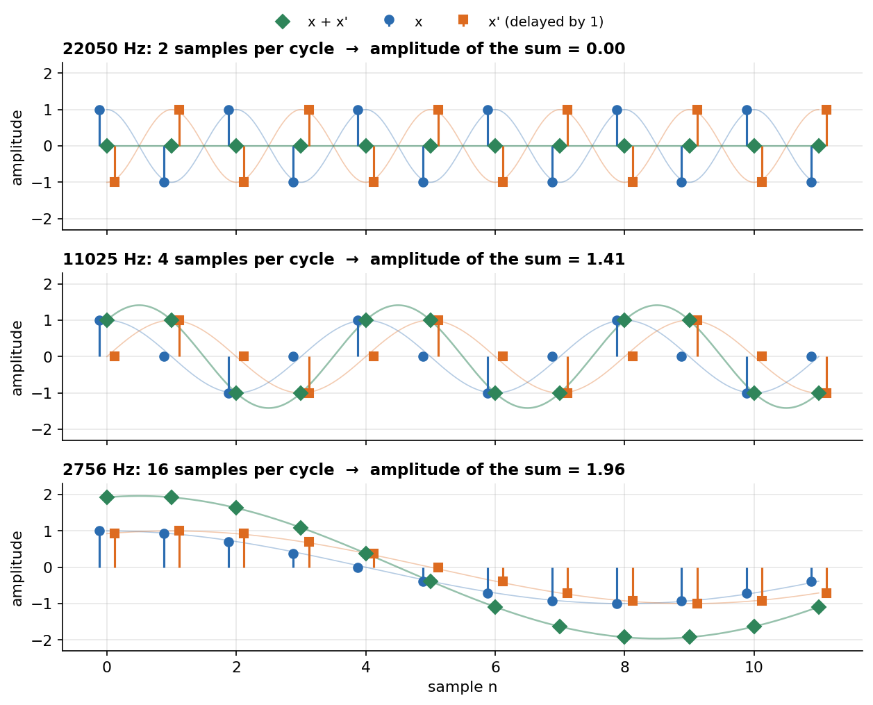
In the middle panel the green diamonds land at ±1, not ±1.41: the samples simply do not fall on the peak of the sum. The thin green curve shows the true amplitude.
And as a gain curve over the whole spectrum:
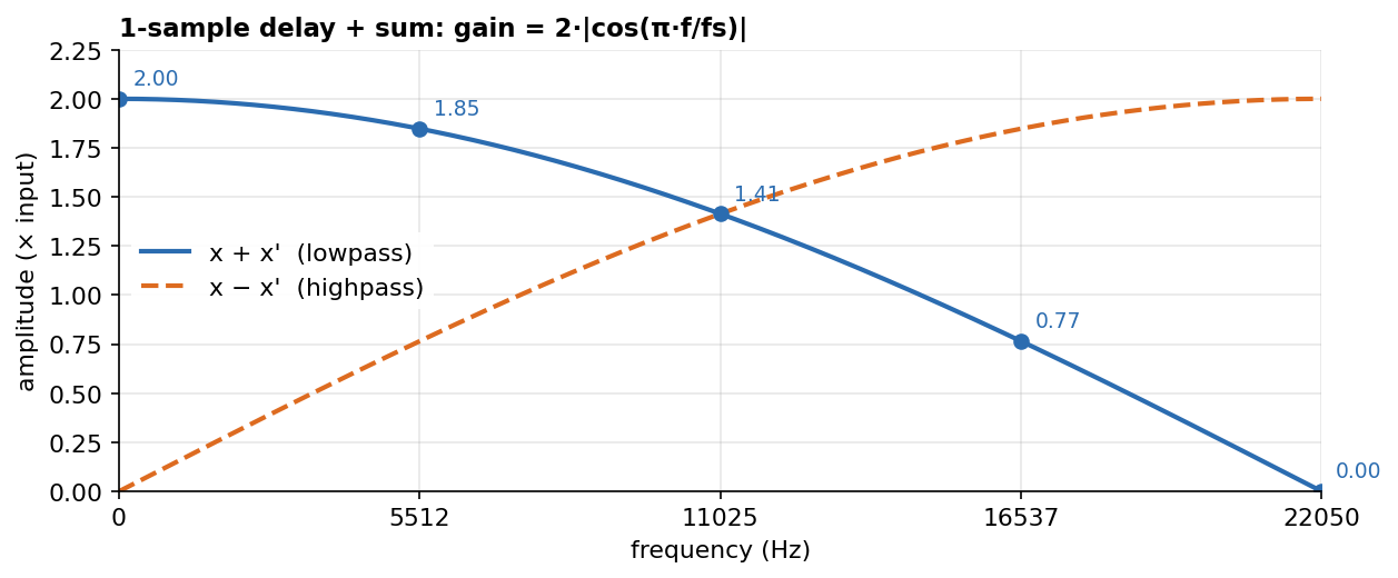
This is a FIR (Finite Impulse Response) lowpass filter. If instead of adding we subtract the copy (x − x'), we turn it upside down ourselves before adding it, and everything flips: a notch at 0 Hz, i.e. a highpass (dashed curve).
import("stdfaust.lib");

// 1-sample delay + sum (lowpass) or subtraction (highpass)
lowpass = _ <: _, mem :> _;           // x + x'
highpass = _ <: _, (mem : *(-1)) :> _; // x - x'

process = lowpass;
1.3 FIR and feedback: zeros and poles
There are two ways of using the delayed copy:
- FIR: the copy is added once. Where the copy arrives upside down, it cancels the original → a zero, i.e. a notch in the spectrum.
- Feedback: the output goes back to the input, so the copy comes back again and again, one lap after the other. Where it comes back in phase, each lap adds to the previous ones and the signal builds up → a pole, i.e. a peak. It does the opposite of a zero.
The sign decides where the effect happens:
with + |
with − |
|
|---|---|---|
FIR x ± x' |
notch at 22050 Hz (lowpass) | notch at 0 Hz (highpass) |
one-pole x ± a·y' |
peak at 0 Hz (lowpass) | peak at 22050 Hz |
Why does the one-pole with − peak at 22050 Hz? The 22050 Hz signal (+1, −1, +1…) arrives inverted after one sample, and the minus sign inverts it again: it comes back in phase and builds up.
FIR and feedback are not symmetric:
- FIR: one copy can cancel another exactly (silence), but as a reinforcement it reaches at most 2 (the original plus one copy).
- Feedback: the signal comes back forever, so the reinforcement accumulates lap after lap. With a feedback coefficient a = 0.9, at 0 Hz it reaches 10 times the input, i.e. +20 dB. But a total cancellation is never possible.
1.4 Why the feedback needs a coefficient
In the feedback, the coefficient keeps the filter from blowing up. Example with a one-pole (y = x + a·y') and a constant input equal to 1 (a “step”):
- without a coefficient (a = 1): each output is “input + previous output”, so 1, 2, 3, 4… it grows forever. With a > 1 it is even worse: it grows exponentially, and keeps growing after the input stops;
- with a = 0.9: only 90% comes back each lap: 1, 1.9, 2.71, 3.44… The steps get smaller and smaller and the output settles at
1 / (1 − a) = 10; - with a = 0.5: it settles at 2, and much faster.
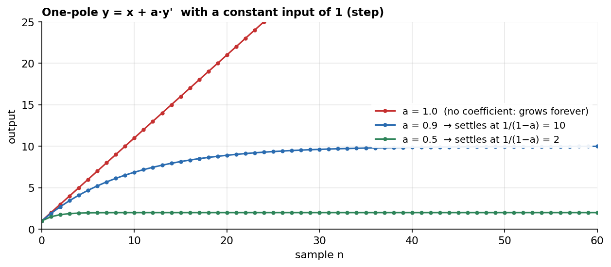
The rule: feedback is stable only if |a| < 1. The closer a is to 1, the higher the peak, and the longer the filter takes to settle (roughly 1/(1 − a) samples: about 10 samples for a = 0.9, 100 for a = 0.99). Remember this “slowness”: it will explain, in section 4, why an allpass delays some frequencies more than others.
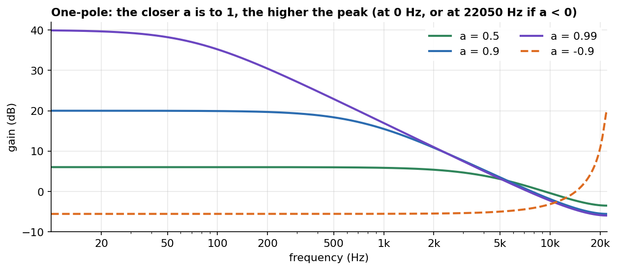
With a negative a (dashed curve) the peak moves to 22050 Hz, as in the table above.
import("stdfaust.lib");

// one-pole: y = x + a * y'   (~ feeds the output back with a 1-sample delay)
onepole(a) = + ~ *(a);

process = onepole(0.9);
So the coefficient decides how deep the notch is (g, in the FIR) or how high the peak is (a, in the feedback), depending on the kind of filter.
Recap of section 1. A delayed copy is an angle that grows with frequency. Added once (FIR) it can cancel exactly: a zero, a notch. Fed back (feedback) it can build up: a pole, a peak. The coefficient sets how strong, and in feedback it must stay below 1.
2. Longer delays: the comb
2.1 The phase grows D times faster
With a delay of D samples, the angle of the copy grows D times faster with frequency:
phase shift = 360° × f × D / fs
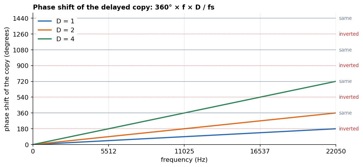
The horizontal lines say what the copy looks like: at 180°, 540°, 900°… it is inverted; at 360°, 720°, 1080°… it is the same again (inverted twice, four times…). 360° is a full turn of the wheel, so the copy lines up with the original again.
- D = 1 only reaches 180°: a single cancellation, at 22050 Hz;
- D = 2 reaches 360°: inverted at 11025 Hz, the same again at 22050 Hz;
- D = 4 reaches 720°: inverted at 5512 and 16537 Hz, the same at 11025 and 22050 Hz.
It helps to check D = 2 sample by sample:
22050 Hz (period 2 samples):  +1 −1 +1 −1 +1 −1
  delayed by 2:                ·  · +1 −1 +1 −1    → identical: reinforcement
11025 Hz (period 4 samples):  +1  0 −1  0 +1  0 −1
  delayed by 2:                ·  · +1  0 −1  0 +1 → inverted: cancellation
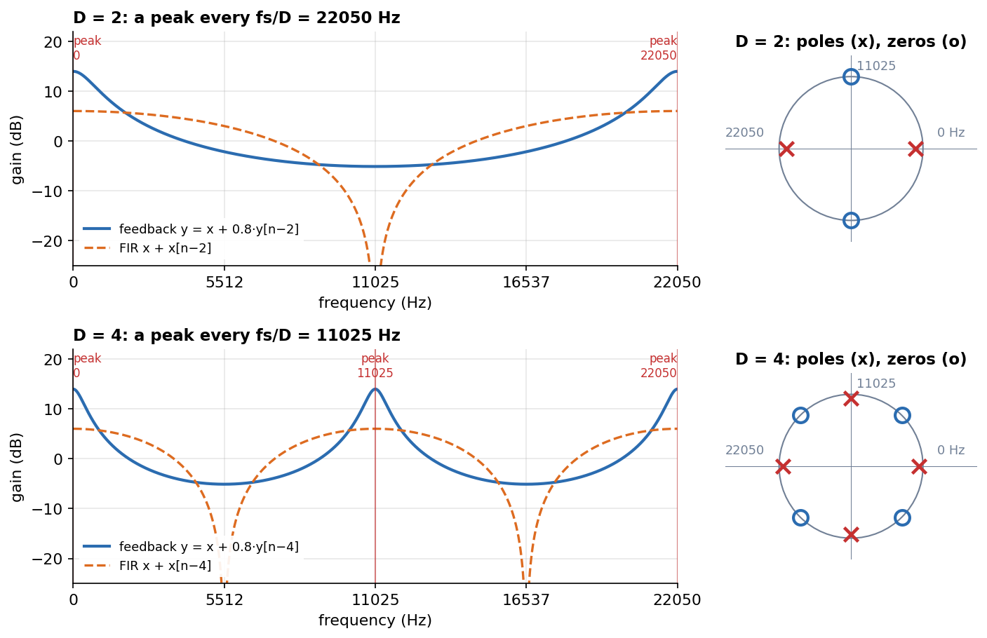
The rule: a frequency is reinforced when, during the delay, it completes a whole number of cycles (0, 1, 2…), because the delayed copy lines up with the original. It is cancelled when it completes a whole number of cycles plus a half. So the peaks of a comb are every fs/D Hz. The longer the delay, the more frequencies fit a whole number of cycles inside it, and the more peaks there are: the “teeth” of the comb.
A common misconception: “if I lengthen the delay by one sample, the peak moves down to half the frequency, then half again.” The peaks do not move down: they multiply, and they are spaced fs/D apart. With feedback
+, D = 1 has a peak at 0 Hz; D = 2 at 0 and 22050 Hz; D = 3 at 0 and 14700 Hz. With feedback−the peaks sit halfway between: D = 1 at 22050 Hz; D = 2 at 11025 Hz; D = 3 at 7350 and 22050 Hz.
2.2 Peaks and notches
With feedback (y = x + g·y[n−D]) the frequencies where the copy comes back the same become peaks (poles). With the FIR (x + x[n−D]) the frequencies where it comes back inverted become notches (zeros). On the right of each row is the “circle” of poles (x) and zeros (o), explained in the next section:
import("stdfaust.lib");

// comb with delay D: feedback (peaks) and FIR (notches)
// ~ already adds 1 sample, so the delay inside the feedback is D - 1
combFB(D, g) = + ~ (@(D - 1) : *(g));   // y = x + g * y[n-D]
combFIR(D) = _ <: _, @(D) :> _;         // y = x + x[n-D]

process = combFB(4, 0.8);
2.3 The circle of poles and zeros
Now that we have FIR, feedback, coefficients and delays, we can read the “circle” (the z-plane). It is a map on which poles and zeros are drawn, and from which the response of a filter can be read:
- The angle on the circle is the frequency. On the right (0°) is 0 Hz, at the top (90°) is 11025 Hz, on the left (180°) is 22050 Hz. It is the same wheel as in 1.1: one sample of delay at 11025 Hz is a quarter turn.
- A pole (x) makes a peak at the frequency of its angle. The closer it is to the edge, the higher and narrower the peak. Towards the centre the peak becomes low and wide. On the edge or outside, the filter becomes unstable: it is the a ≥ 1 case of 1.4.
- A zero (o) makes a notch at the frequency of its angle. If it sits exactly on the edge, the notch is total (silence). The further it moves away from the edge, the shallower the notch.
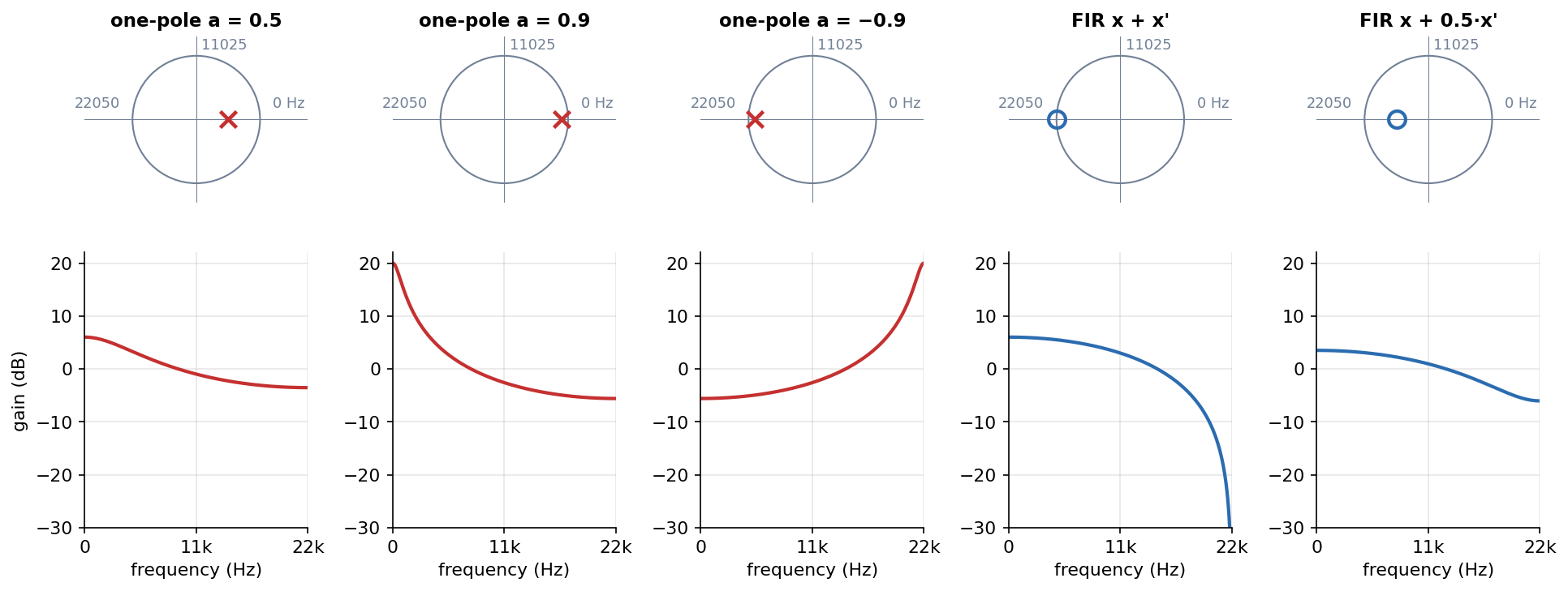
From left to right:
- one-pole a = 0.5: the pole is halfway towards 0 Hz, so the peak is low and wide;
- a = 0.9: the pole is close to the edge, so the peak is high (+20 dB) and narrow;
- a = −0.9: the same pole, but on the left, so the peak moves to 22050 Hz;
- FIR x + x’: a zero on the edge at 22050 Hz, total notch;
- FIR x + 0.5·x’: a zero inside the circle, partial notch.
In the D = 4 comb above there are 4 poles spread around the circle (0, 11025, 22050 Hz, plus the mirror of 11025 Hz below) and 4 zeros halfway between them. The delay D decides how many poles and zeros there are and where they sit (every 360°/D). The coefficient decides how close they are to the edge.
The lower half of the circle mirrors the upper half: for a real signal it holds the same information. It is the same mirror as in the next section.
2.4 Above 22050 Hz: the mirror (aliasing)
The phase count could go on above 22050 Hz: with D = 2 there would be a cancellation at 33075 Hz and the phase would line up again at 44100 Hz. But in the digital world those frequencies do not exist as different frequencies: two sinusoids at f and at fs − f produce exactly the same samples.
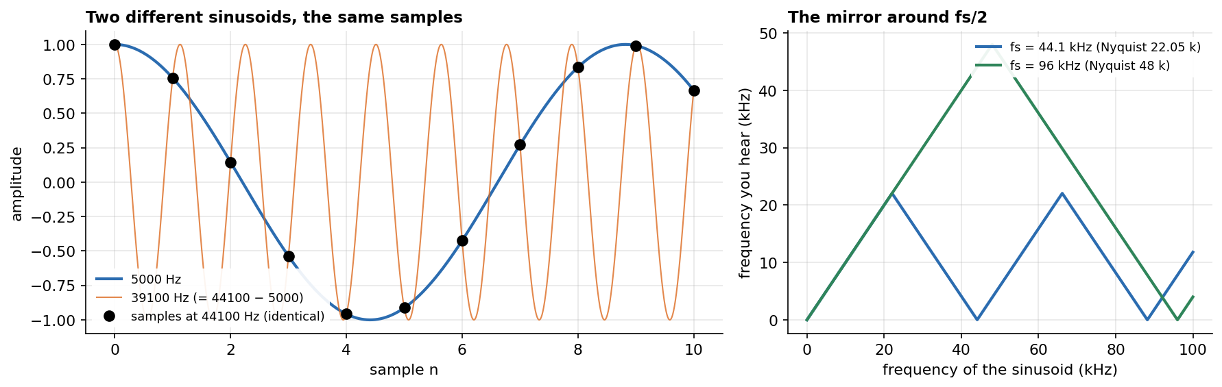
On the left: at 44100 Hz, a 5000 Hz sinusoid and a 39100 Hz one (= 44100 − 5000) go through the same points. The digital system only sees the samples, so it cannot tell them apart. That is why everything above fs/2 folds back as in a mirror: 33075 Hz behaves like 11025 Hz. Looking from 0 to fs/2 is enough.
What about 96 kHz or 192 kHz? It works the same way, but the mirror moves: it always sits at half the sampling rate. On the right of the plot: at 44.1 kHz the folding happens at 22.05 kHz, at 96 kHz at 48 kHz (at 192 kHz it would be at 96 kHz). So:
- every rule in these notes holds, as long as frequencies are measured as a fraction of fs (0 Hz, fs/4, fs/2…);
- one sample lasts less time: at 96 kHz about 10 µs instead of 23 µs. The lowpass
x + x'has its notch at fs/2 = 48 kHz, outside the audible range, and is almost flat in the audio band. To get the same filter in Hz, the delays must be doubled (or the coefficients recalculated); - the advantage of a high fs is more room above the audible range before the mirror.
3. The allpass
An allpass is a filter with the same amplitude at every frequency that still changes the signal: it changes its phase. To see how that is possible, look at its topology. It contains:
- a FIR part (direct signal + delayed signal, with a certain sign) that creates notches;
- a part that feeds back and fills exactly those notches with poles.
The result is a flat filter: the same amplitude at every frequency.
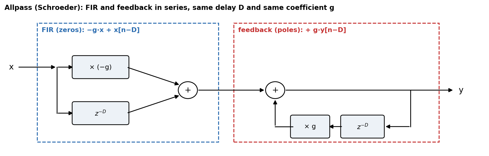
Reading the diagram from the left:
- FIR part (blue): the signal splits in two: one part is multiplied by −g, the other is delayed by D samples. They are added once:
−g·x + x[n−D]. It is a FIR comb, so it makes notches every fs/D Hz. - Feedback part (red): the output comes back delayed by D samples, multiplied by g, and is added to the input:
+ g·y[n−D]. It is a feedback comb, so it makes peaks every fs/D Hz, in the same places as the notches.
The two parts on their own, and the result:
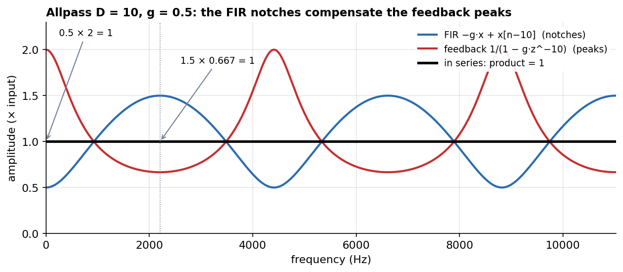
At 0 Hz the FIR has a notch (0.5) and the feedback a peak (2): 0.5 × 2 = 1. At 2205 Hz the FIR has a peak (1.5) and the feedback a notch (0.667): 1.5 × 0.667 = 1. And so on at every frequency, so the black line is flat.
Two important points:
-
FIR and feedback are in series, not in parallel. The signal goes through the FIR first and then through the feedback. In series the gains multiply (notch 0.5 × peak 2 = 1). In parallel they would add up, and nothing would compensate. In the classic diagram the two parts share the same delay line to save memory, so they look like a single block, but they are two pieces in series.
A common misconception: “two separate branches leave x: one is a FIR with delay D and gain g that makes the zeros, the other is a feedback with the same D and g that makes the poles, and they cancel each other.” The idea of poles and zeros compensating is right, but the two parts are one after the other (series), not side by side. And, as the next point shows, they do not cancel completely.
-
The FIR coefficients are swapped. The allpass FIR is “first −g, then 1”, while the feedback is “1, then −g”. It is the same FIR, reversed in time. A signal reversed in time has:
- the same amplitude at every frequency, so the same notches;
- a different phase.
If the FIR were identical to the feedback (1, …, −g), it would remove the signal before it enters the loop, and the loop would have nothing left to build up: everything would cancel, amplitude and phase. What remains is a wire, which is useless. With the reversed FIR the notches are the same, but the phase is not:
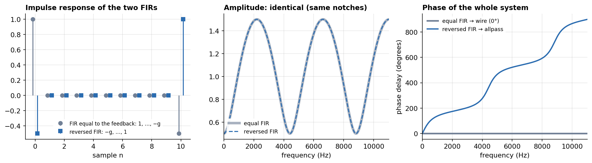
The amplitude compensates, the phase does not. The allpass only changes the phase. This is the most important idea in these notes.
The compensation happens over time: the impulse response is a tail (−0.5, 0.75, 0.375, 0.188… every D samples), not a single impulse. On transients you can hear it; on steady sinusoids the volume is flat.
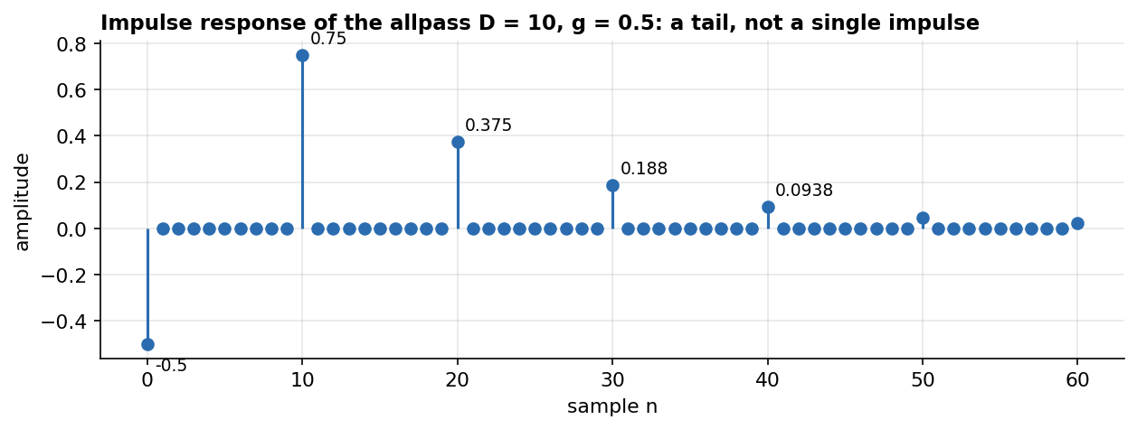
import("stdfaust.lib");

// Schroeder allpass: FIR and feedback in series, same delay D and same g
D = 10;
g = 0.5;
fir = _ <: *(-g), @(D) :> _;          // -g * x + x[n-D]     (the zeros)
iir = + ~ (@(D - 1) : *(g));          // y = in + g * y[n-D] (the poles)
allpass = fir : iir;

// with the FIR equal to the feedback (1, ..., -g) poles and zeros cancel: a wire
firSame = _ <: _, (@(D) : *(-g)) :> _;
wire = firSame : iir;

process = allpass;
A question that comes up: “So an allpass is just a neutral delay?” Not quite. If you mix it with the dry signal you do get notches, as with a comb. But an allpass is not a delay of a fixed time: it is a delay that is different at every frequency. That is what the next section is about.
4. Time delay and phase in degrees are two different things
When a frequency comes out “late”, two different things can be measured:
- the time delay: how long after the input it arrives (in samples or ms);
- the phase delay: how many degrees behind the input it is.
They are linked by:
phase delay (degrees) = 360° × f × time delay (samples) / fs
The same time delay gives different angles at different frequencies: 1 sample is a lot for a fast frequency and very little for a slow one (the wheel of 1.1).
- Pure delay: every frequency arrives after the same time, so the angle grows in a straight line (the lines of section 2). Mixed with x it gives the comb: fixed, evenly spaced notches.
- Allpass: every frequency arrives after a different time.
4.1 Why different times: two roads
First-order allpass with c = −0.9 (the 1-sample allpass used in phasers):
y[n] = −0.9·x[n] + x[n−1]  +  0.9·y[n−1]
       └──── fast road ────┘   └─ slow road ─┘
- The slow road is a one-pole lowpass (the loop with +0.9 from 1.4). The lows go round the loop and build up, but building up takes time (about 10 samples for a = 0.9), so they come out late.
- The fast road is the direct FIR. In the loop, the highs flip sign at each lap and die out, so they come out almost only through the direct road: at once.
- “Flat” says how much comes out, not when. Part of the signal travels fast, part slowly.
You can see it with the step response (input jumping from 0 to 1):
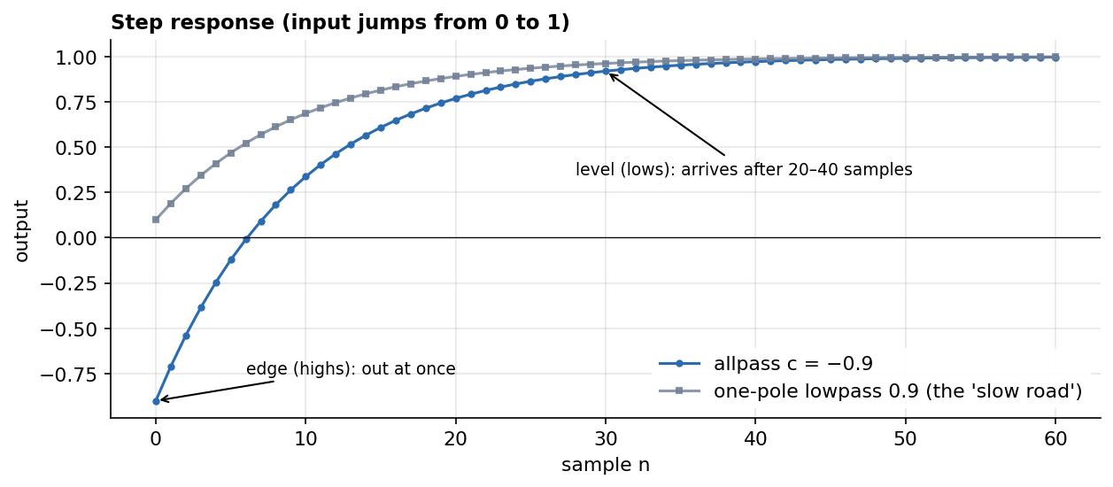
The edge of the step (highs) comes out at once, at −0.9. The level (lows) arrives after 20–40 samples, as slowly as the one-pole.
The same can be measured frequency by frequency: how long each frequency takes to come out (this is called group delay):
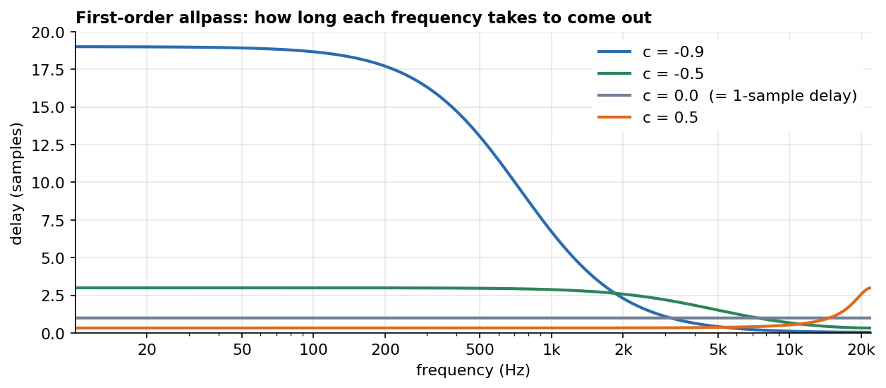
- with c = −0.9 the lows come out after 19 samples, the highs almost at once;
- with c = 0 every frequency comes out after 1 sample: it is a delay;
- with c = 0.5 it is the other way round: the highs come out late (the pole is towards 22050 Hz).
Where the loop resonates, the signal stays in it for a long time, so it comes out late. The FIR can compensate the height of the peak, but it cannot make the loop release earlier what it holds: to do that it would need to know the future.
import("stdfaust.lib");

// first-order allpass: H(z) = (c + z^-1) / (1 + c z^-1)
// y = c * x + x' - c * y'   (c = 0: a 1-sample delay)
ap1(c) = _ <: *(c), mem :> (+ ~ *(-c));

process = ap1(-0.9);
A question that comes up: “If the filter is flat and the poles fill the notches, why should different frequencies have different delays?” Because flat amplitude only means that, in the end, the same amount of each frequency comes out. The frequencies near the pole get there by going round the loop many times; the others take the direct road. Same amount, different travel time.
4.2 A sinusoid through the allpass
Send a sinusoid x through the allpass and compare the output with the direct x:
- at 0 Hz they are in phase;
- going up in frequency, the output is more and more delayed, in degrees;
- at 22050 Hz it is half a cycle (180°) behind;
- the amplitude is always the same.
The first-order allpass has the same start and end points as the 1-sample delay (0° and 180°). What changes is the road in between:
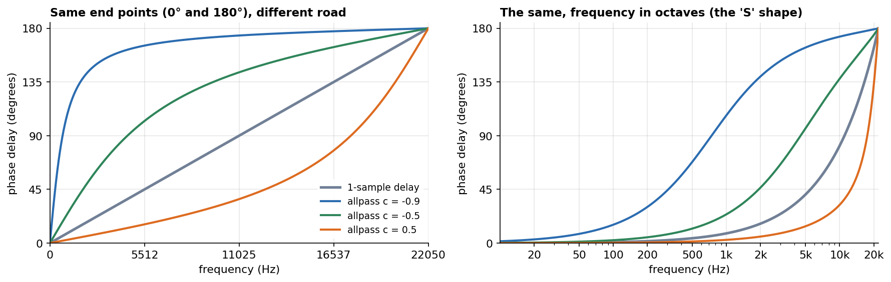
On the left with a linear frequency axis, on the right in octaves (like the display of an EQ). With c = 0 the allpass is exactly the 1-sample delay (the grey line).
Watch out, time versus degrees. With c = −0.9 the lows have a lot of time delay (19 samples) but few degrees: a cycle at 100 Hz lasts 441 samples, so 19 samples are only 15°. The highs have almost no time delay but many degrees. “The lows are the most delayed” is true in time and false in degrees.
On the octave axis (right) each curve looks like a stretched S: flat in the lows, steep around one frequency, flat again near 180°. The steep part is where the pole acts, and c moves it left or right.
A comb made allpass (D = 10) has different phase delays in different parts of the spectrum, in correspondence with the poles of the comb (0, 4410, 8820… Hz):
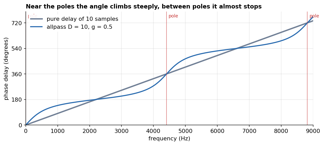
The allpass goes through the same points as the delay (0°, 180°, 360°…), but near the poles the angle climbs steeply and between poles it almost stops.
Rule: where there is a pole, the angle climbs steeply with frequency, because there the signal has a lot of time delay. The coefficient moves the pole, and with it the climbing zone.
4.3 The phaser
Allpass + dry signal → a notch where the angle of the allpass is 180° (the two are in opposite phase). Since c moves the curve, c moves the notch:
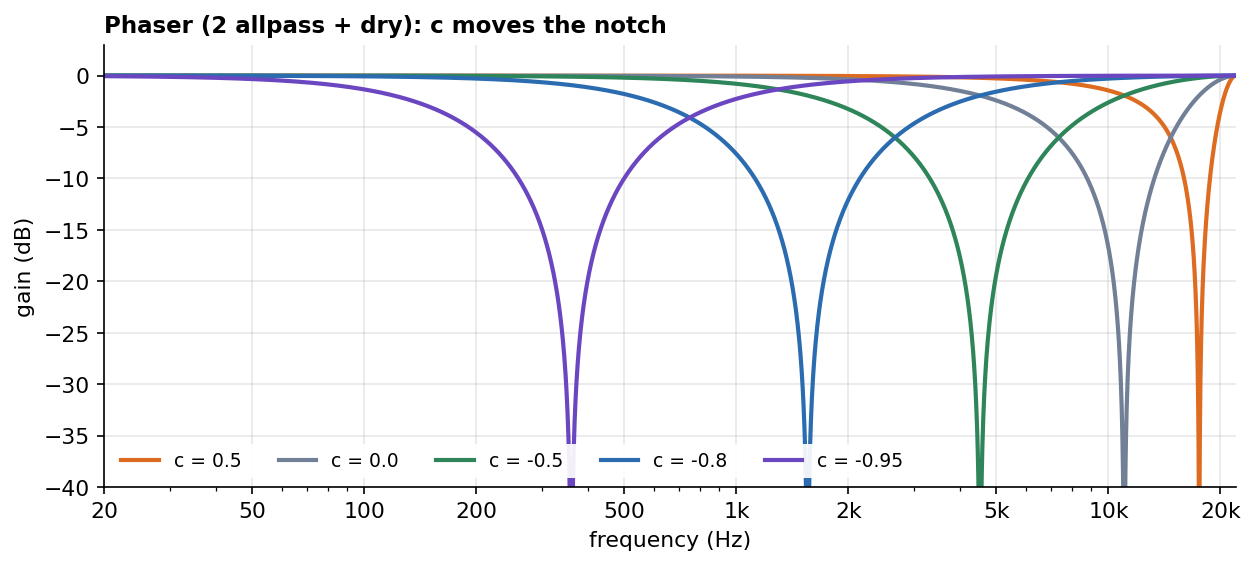
With c = 0 the two allpass are two samples of delay, and the notch at 11025 Hz is exactly the one of the D = 2 FIR comb of section 2.
- comb = the same time for every frequency → fixed notches;
- phaser = a different time for each frequency → notches that move.
import("stdfaust.lib");

ap1(c) = _ <: *(c), mem :> (+ ~ *(-c));

// minimal phaser: 2 allpass + dry, c moves the notch
phaser(c) = _ <: _, (ap1(c) : ap1(c)) :> *(0.5);

process = phaser(-0.5);
Try it. Listen to the difference on noise: on the left a comb (dry + 8-sample delay), on the right a phaser (dry + 4 allpass). Move c and only the right channel changes.
import("stdfaust.lib");

ap1(c) = _ <: *(c), mem :> (+ ~ *(-c));

// left: dry + pure delay = comb (same time for every frequency: fixed, evenly spaced notches)
// right: dry + 4 allpass = phaser (different time per frequency: notches move with c)
comb(D) = _ <: _, @(D) :> *(0.5);
phaser4(c) = _ <: _, seq(i, 4, ap1(c)) :> *(0.5);

c = hslider("c", -0.7, -0.99, 0.99, 0.01) : si.smoo;
process = no.noise * 0.5 <: comb(8), phaser4(c);
5. The goal: the same angle at every frequency
A phase shifter wants to move every frequency by the same angle. For 90°, a quarter of a cycle, the delay would have to equal a quarter of the period of each frequency:
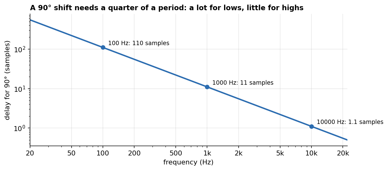
110 samples at 100 Hz, 11 at 1000 Hz, 1.1 at 10000 Hz: the lows delayed a lot, the highs almost not at all. A delay cannot do it, because it gives every frequency the same time.
One allpass cannot do it either. It does hold the lows longer than the highs, so it goes in the right direction, but its curve crosses 90° at a single frequency:
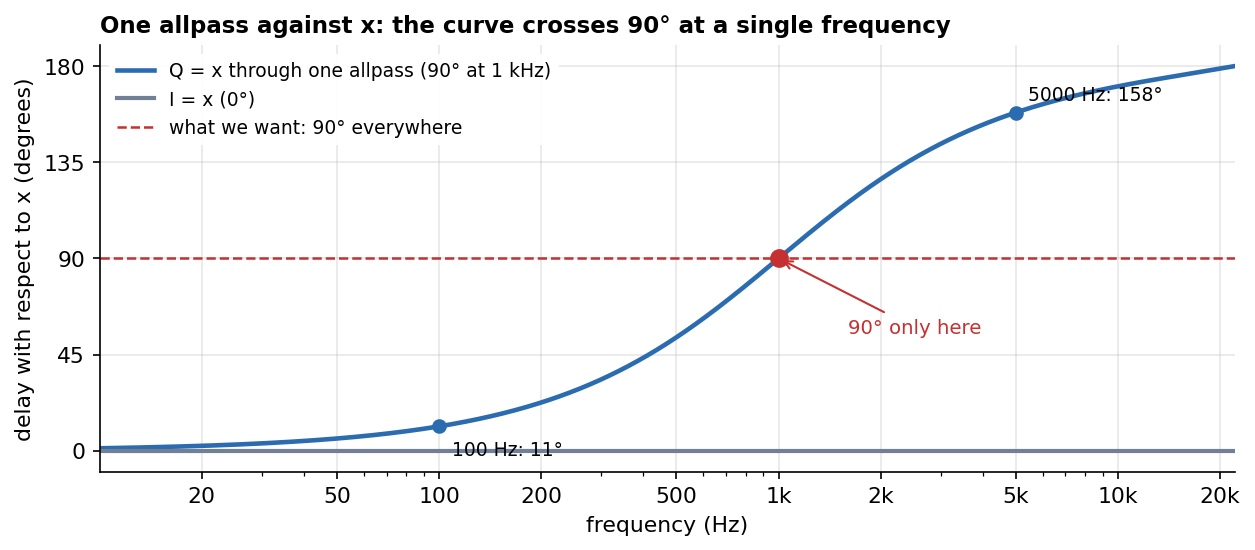
With an allpass tuned to give 90° at 1 kHz, the output is only 11° behind x at 100 Hz and 158° behind at 5000 Hz.
The solution splits into two separate problems, which the next two sections solve one at a time:
- Section 6: if we already had the signal at 0° and the same signal at 90° (at every frequency), how would we get any other angle? Answer: a crossfade.
- Section 7: how do we get the signal at 90°? Answer: with two allpass chains, not one.
6. The crossfade
Step 1: two ingredients
Suppose we have two signals:
- I = the signal at 0° (I for in-phase);
- Q = the same signal at 90°, i.e. delayed by a quarter cycle, at every frequency (Q for quadrature, which means “at 90°”).
How to build Q is the topic of section 7. For now, imagine we have it.
Step 2: mix them with two weights
y = I·cos(θ) + Q·sin(θ)
It is a crossfade between I and Q in which the two volumes come from the circle:

| θ | weight of I | weight of Q | output |
|---|---|---|---|
| 0° | 1 | 0 | I only |
| 45° | 0.707 | 0.707 | half and half → delayed by 45° |
| 90° | 0 | 1 | Q only |
| 180° | −1 | 0 | I upside down |
| 270° | 0 | −1 | Q upside down (270° of delay) |
| 360° | 1 | 0 | I again: a full turn |
With the negative weights (I upside down is “180°”, Q upside down is “270°”) the crossfade covers the whole turn, not only 0° to 90°.
Step 3: why the phase lands “in between”
Two sinusoids of the same frequency, added together, give another sinusoid of that frequency, with a phase in between. The more weight we give to Q, the closer we get to “90° of delay”:
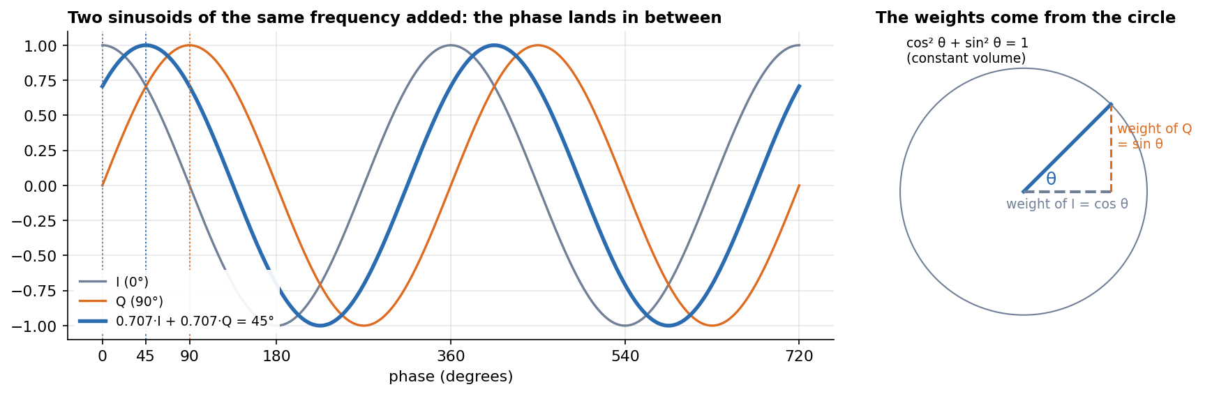
It is the arrow sum of 1.2 again: I and Q are two arrows at right angles on the wheel, and weighting them with cos θ and sin θ gives an arrow at angle θ. In trigonometry this is cos(a − θ) = cos(a)·cos(θ) + sin(a)·sin(θ): to shift a cosine by θ, all you need is the cosine itself (I) and its 90° version (Q), mixed with cos θ and sin θ.
Step 4: why cos and sin
cos and sin keep the volume constant, because cos² θ + sin² θ = 1 (Pythagoras on the circle). It is the same law as an equal-power pan. With a linear crossfade, halfway (45°) the volume would drop.
Step 5: why it works at every frequency
The weights cos θ and sin θ do not depend on frequency: they are just two volumes. So every frequency is shifted by the same θ. And the time adapts by itself:
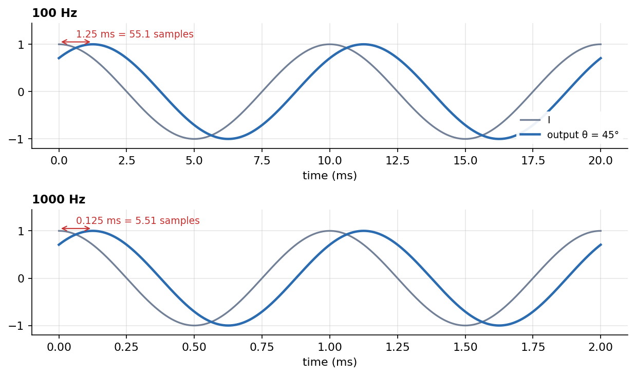
45° is 55 samples at 100 Hz and 5.5 samples at 1000 Hz. That is exactly the “lows delayed a lot, highs a little” of section 5. The hard work, the frequency-dependent part, is done once, when building Q. After that, changing θ means turning two volume knobs.
Step 6: the sign
y = I·cos θ + Q·sin θdelays by θ. This is the version used in the code: the “Phase Shift” slider at 90 means 90° of delay.y = I·cos θ − Q·sin θ(with a minus) turns the wheel the other way: it advances by θ. Musically it is the same (advancing by 90° = delaying by 270°), but if the slider must be a delay, the sign must be+.
import("stdfaust.lib");

// crossfade: from I (0 degrees) and Q (90 degrees) to any angle
// y = I * cos(theta) + Q * sin(theta): delays by theta degrees
rotate(degrees) = *(cos(theta)), *(sin(theta)) :> _
with {
    theta = degrees * ma.PI / 180.0;
};

process = rotate(hslider("Phase Shift [unit:°]", 45.0, 0.0, 360.0, 1.0) : si.smoo);
Analogy: the Hilbert transform builds two loudspeakers, one at 0° and one at 90°. The crossfade is the pan that places the sound anywhere around the circle. Without the crossfade we would only have 0° or 90°.
Building Q is called the Hilbert transform. So the second problem is: build Q.
Questions that come up
“If the allpass chains already make the 90°, what does the crossfade control?” The angle of the output. The allpass chains give two fixed references (0° and 90°); the crossfade, i.e. the slider, chooses where to be between and around them.
“With a single stage, can I control at most 90°?” No. 90° is the fixed distance between I and Q, not the range of the slider. Thanks to the negative weights, a single stage covers the whole turn, 0–360°.
“If I set 1080°, is the output three cycles behind?” On a steady sinusoid, three whole cycles behind is identical to the original: phase lives on a circle, and 1080° = 3 turns = 0°. A phase shifter cannot delay the attack of a sound by three cycles, because three cycles last 30 ms at 100 Hz but 3 ms at 1 kHz. That would be a delay of a different time at every frequency, a different device. What a range larger than 360° does give, in a feedback loop, is a longer sweep: while θ moves through 1080°, every phase relation is crossed three times.
7. Building I and Q
Step 1: a perfect Q does not exist
A constant (0 Hz) has no cycles, so it cannot be “a quarter cycle late”. And near 0 Hz the delays would become huge (plot of section 5): 90° is about 11000 samples at 1 Hz, 110000 at 0.1 Hz… a filter that holds the signal forever. So we accept that below ~20 Hz it does not work (and, by the mirror of 2.4, near 22050 Hz).
Step 2: the trick, do not compare with x
The crossfade only uses I and Q, never x. So we do not need Q to be 90° behind x: we need Q to be 90° behind I. And I does not have to be x.
So x goes through two different chains of allpass. With respect to x, both shift the phase in a frequency-dependent way. Between them, though, they always stay 90° apart, like the two rails of a railway: they bend, but the distance between them stays the same.
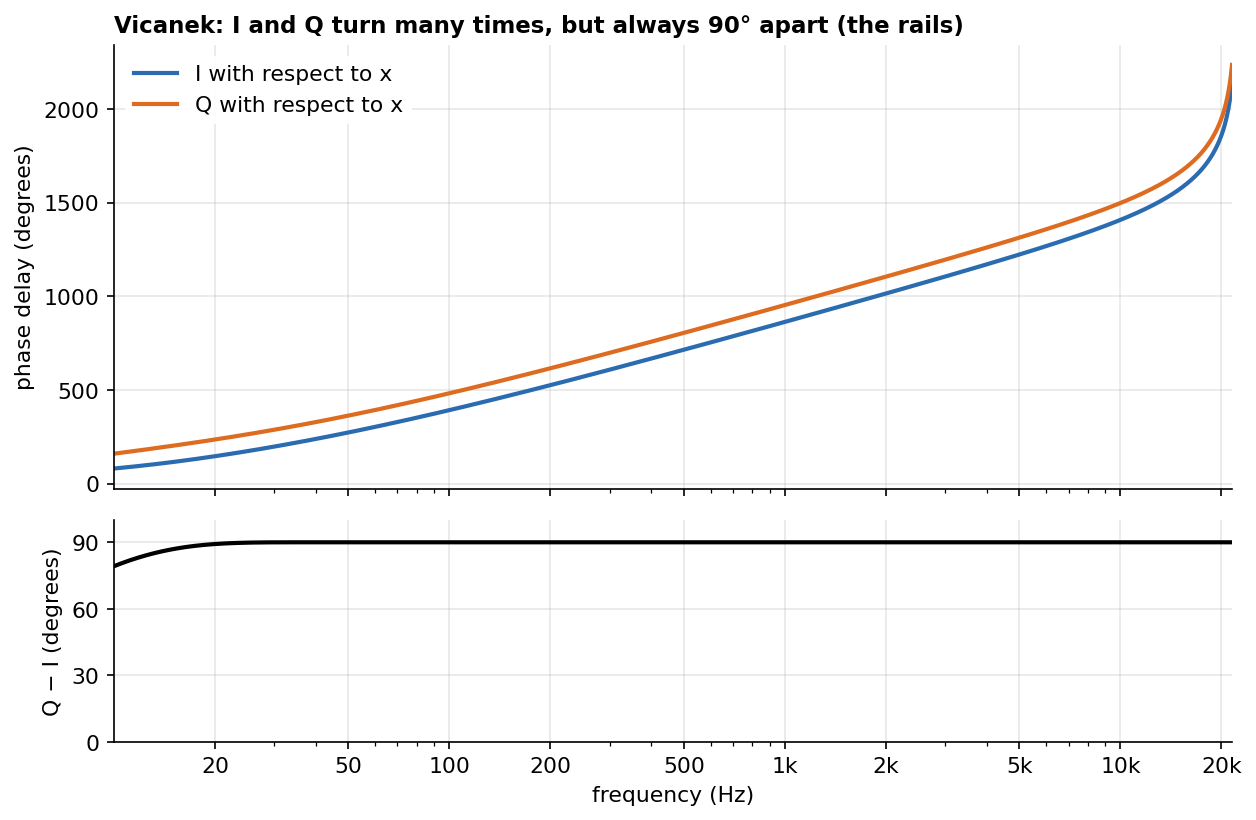
For example: at 100 Hz I is 392° behind x and Q 482°; at 1000 Hz 863° and 953°; at 5000 Hz 1223° and 1313°. Always 90° apart.
The consequence: the output is shifted by θ with respect to I, not with respect to x. With θ = 0 we do not get x back, but x after the allpass chain. When comparing or measuring, the right reference is I.
Step 3: how the two curves are kept “parallel”
- Allpass filters in series add their angles. If the first delays a frequency by 30° and the second by 50°, together they make 80°.
- Each allpass makes a climb of 180° around its pole (section 4).
- The climbs alternate between the two branches: Q makes each climb half a step before I. Half a climb = 90°.
Start with a single pair: Q’s pole low (~400 Hz), I’s pole high (~2400 Hz):
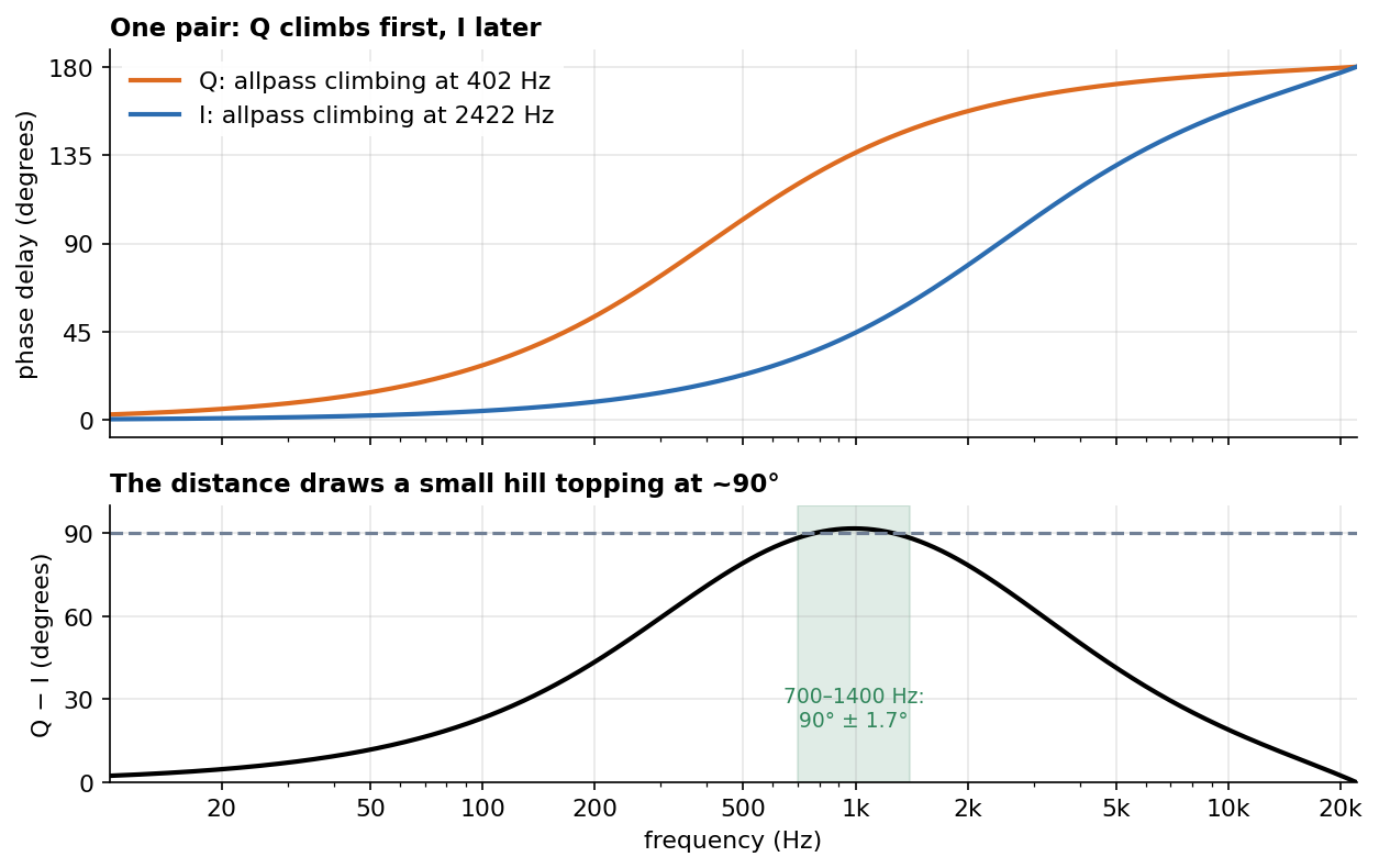
- in the lows neither has climbed yet, so they are close;
- in the middle Q has already climbed and I has not yet: distance ~90°;
- in the highs both have climbed, so they are close again.
The distance draws a small hill topping at ~90°. Between 700 and 1400 Hz this is already a phase shifter (maximum error 1.7°), but over a single octave.
More alternating pairs widen the good zone:
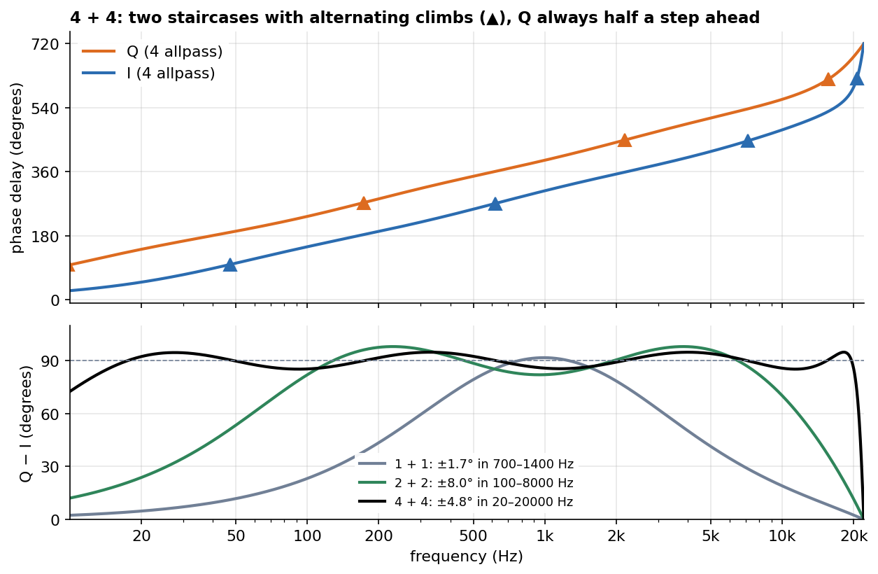
Top: with 4 allpass per branch the climbs (▲) alternate, Q, I, Q, I… from lows to highs, and Q always stays half a step ahead. Bottom, the distance between I and Q:
- 1 + 1: ~90° (± 1.7°) only between 700 and 1400 Hz;
- 2 + 2: ± 8° between 100 and 8000 Hz;
- 4 + 4: ± 4.8° between 20 and 20000 Hz.
(examples with 1-sample allpass, coefficients optimised by computer)
Step 4: the two blocks of the phase shifter
x ──► [many allpass, fixed coefficients c] ──► I ──► ×cos θ ──┐
  └─► [many allpass, other fixed c]        ──► Q ──► ×sin θ ──┴─(+)──► output
          └── Hilbert: builds the 90° ──┘           └── crossfade: chooses θ ──┘
- Hilbert is fixed. Its calibration is the set of coefficients c, which decide where the poles are, i.e. where the climbs happen. They are not computed by hand: an optimisation finds them (Niemitalo used a genetic algorithm, Vicanek a numerical optimisation, Laurent de Soras’ hiir library a design formula).
- Crossfade:
cosandsinonly choose θ. It is the “Phase Shift” slider.
A common confusion: “so the phase shifter is many allpass filters calibrated with sine and cosine?” No: the two parts are separate. The calibration of the 90° is done by the coefficients of the allpass filters. Sine and cosine appear only in the crossfade, as the two volumes that choose θ.
Step 5: the brick of the code, a 2-sample allpass
In the code the “brick” is not the 1-sample allpass of the examples, but a 2-sample one:
tf(c, y, x) = c * (x + y') - x''; // used as tf(c) ~ _
~ _ feeds the output back with a 1-sample delay, so inside tf y' is the output from 2 samples ago and x'' the input from 2 samples ago:
y[n] = c·x[n] − x[n−2]  +  c·y[n−2]
       └─ FIR (fast) ─┘    └ loop (slow) ┘
It is the Schroeder allpass of section 3 with D = 2: FIR and loop with the same coefficient, the FIR reversed (with the sign flipped: at 0 Hz each section turns the signal upside down, but with an even number of sections the inversions cancel out). And from section 2 we know that a loop with D = 2 resonates at 0 Hz and at 22050 Hz at the same time. So each section makes the same climb as the 1-sample allpass in the lows, plus a second, mirrored climb towards 22050 Hz:
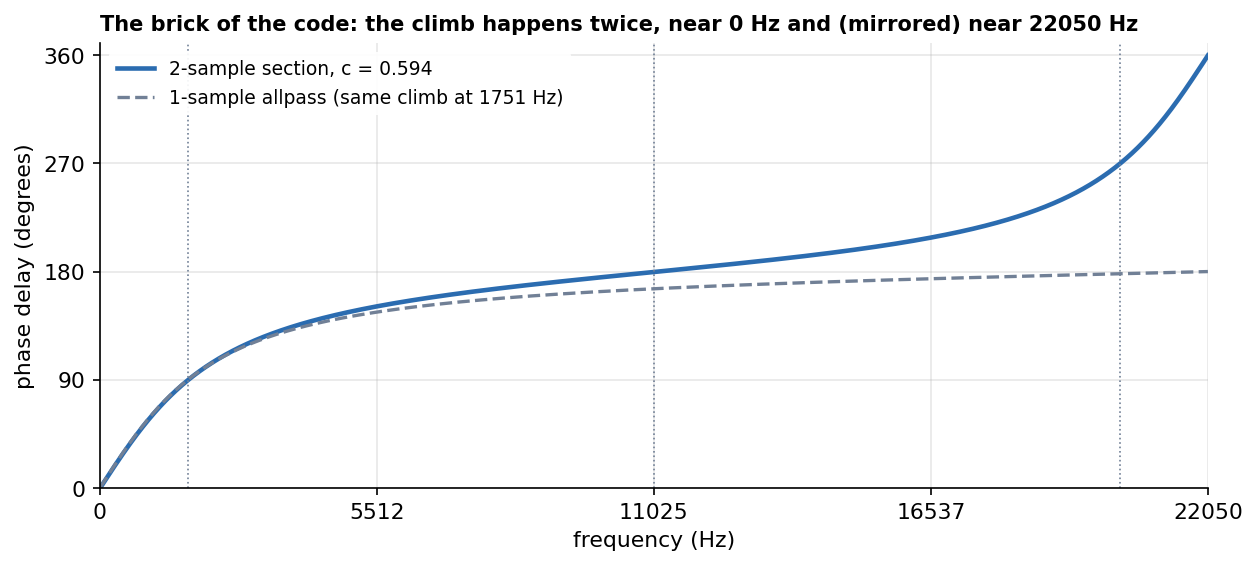
This is why the Hilbert of the code works poorly both near 0 Hz and near 22050 Hz: the mirror.
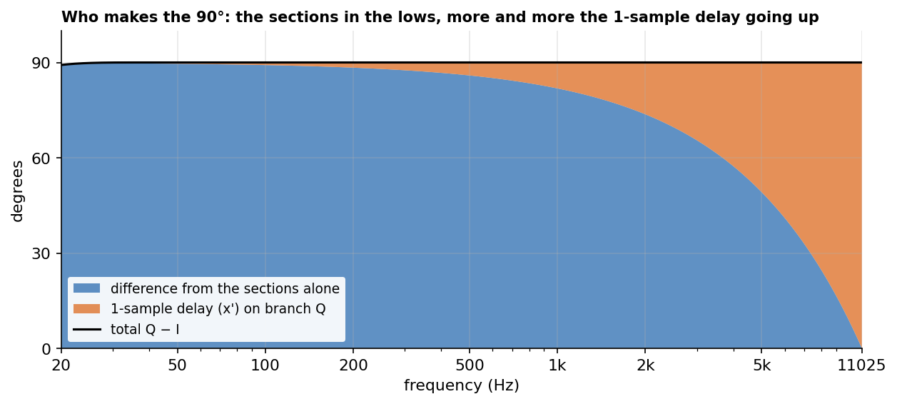
The Q branch has an extra 1-sample delay (x'). At 11025 Hz two samples are half a cycle, so every section is transparent there: the only difference between I and Q is x', and at 11025 Hz one sample is exactly 90° (the wheel of 1.1). In the lows the sections make almost all of the 90°; going up, more and more of it comes from x':
8. Vicanek’s improvement
The structure is the same (same brick, two branches, crossfade). Only the number of allpass and the coefficients change, computed for a higher order. As Oleg Nesterov points out in the mailing-list thread, Niemitalo’s and Vicanek’s filters belong to the same family (polyphase half-band IIR, like the hiir library). Vicanek computed and published one set of coefficients for 8 + 8 allpass: one among many possible.
Why “many possible”? A designer like hiir asks for two things: how many allpass to use, and how far the filter must work, i.e. how close to 0 Hz and to Nyquist. With a fixed number of climbs one can either concentrate them in the middle of the band (the distance stays extremely close to 90°, but the filter gives up earlier in the deep lows) or spread them towards the lows (it works lower, but the distance wobbles more around 90°). Each choice gives a different set of coefficients.
| allpass per branch | maximum error on the 90° | |
|---|---|---|
| Niemitalo | 4 + 4 | ~0.7° |
| Vicanek | 8 + 8 | ~0.001° (above ~35 Hz) |
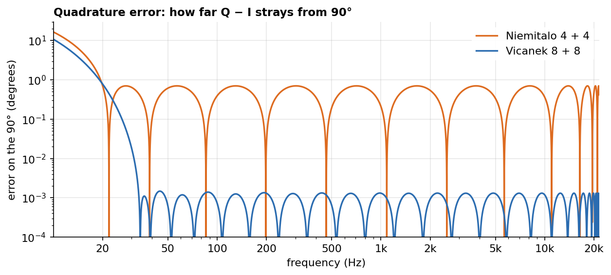
More climbs, closer together, make the distance smoother and closer to 90°:
- Niemitalo wobbles by ±0.7° over the whole band;
- Vicanek stays below 0.0015° from ~35 Hz up;
- below ~20 Hz both give up in the same way. Vicanek used the extra sections to be more precise, not to reach lower.
When does it matter?
- Slider still: almost inaudible. 0.7° of error changes the volume by about ±0.05 dB as θ varies.
- θ moving (the phase shifter becomes a frequency shifter, see “Try it” below): the error creates a “ghost copy” shifted in the wrong direction. In the worst case it is at −44 dB with Niemitalo and −98 dB with Vicanek (measured with a 1 kHz sine shifted by +100 Hz: −55 dB versus −99 dB).
- Many stages in cascade: the errors add up.
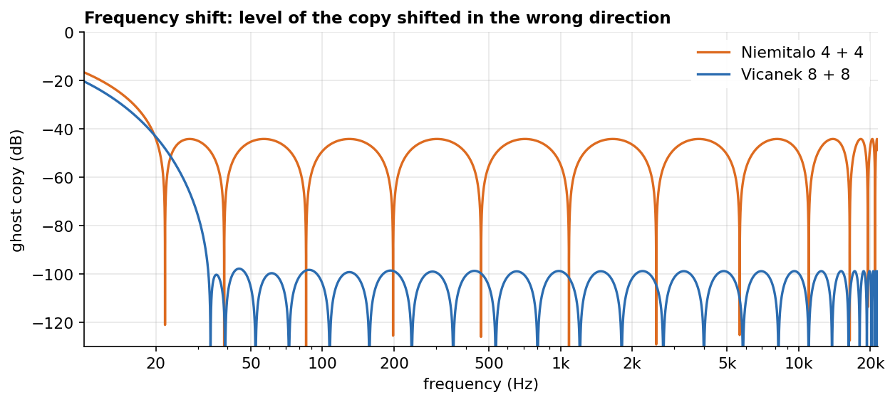
The price: roughly twice the CPU, and the lows come out a little later (more allpass, more “slow road”). At 30 Hz the I branch delays by about 318 samples with Niemitalo and 558 with Vicanek; at 1 kHz about 13 versus 27.
The code: Hilbert_Vicanek_Phase_Shifter.dsp
Hilbert transform with Vicanek’s coefficients. It has a single stage (slider 0–360°) and a version with N stages in cascade (slider 0–1080°, divided among the stages). It outputs both the reference (real branch, 0°) and the rotated signal; in an acoustic feedback loop (one microphone, one loudspeaker) only the rotated signal is used.
import("stdfaust.lib");

// Phase shifter using the Hilbert transform
// Martin Vicanek coefficients (8 + 8 allpass)
// Phase Shifter Using a Hilbert Transformer
hilbertPHshift(degrees, x) = realPH, output
with {
    analytic(x) = real, imaginary
    with {
        re_c = (0.0406273391966415,
                0.2984386654059753,
                0.5938455547890998,
                0.7953345677003365,
                0.9040699927853059,
                0.9568366727621767,
                0.9815966237057977,
                0.9938718801312583);
        im_c = (0.1500685240941415,
                0.4538477444783975,
                0.7081016258869689,
                0.8589957406397113,
                0.9353623391637175,
                0.9715130669899118,
                0.9886689766148302,
                0.9980623781456869);
        tf(c, y, x) = c * (x + y') - x'';
        real =      x  : seq(i, 8, tf(ba.take(i + 1, re_c)) ~ _);
        imaginary = x' : seq(i, 8, tf(ba.take(i + 1, im_c)) ~ _);
    };
    realPH = x : analytic : _, !;
    quadraturePH = x : analytic : !, _;
    output = realPH * cos((degrees * ma.PI / 180.0)) + quadraturePH * sin((degrees * ma.PI / 180.0));
};
HilbertPhaseShifter = hilbertPHshift(hslider("Phase Shift °", 0.0, 0.0, 360.0, 1.0) : si.smoo);

// N stages in cascade: each stage rotates by (slider / N), total N * (slider / N) = slider
// reference: x passed N times through the real branch (0° rotation)
N = 6;
HilbertPhaseShifterN = _ <: seq(i, N, hilbertPHshift(0.0) : _, !),
                            seq(i, N, hilbertPHshift(degreesN) : !, _)
with {
    degreesN = hslider("Phase Shift N°", 0.0, 0.0, 1080.0, 1.0) / N : si.smoo;
};

//process = co.compressor_mono(6, -18, 0.001, 0.05) : HilbertPhaseShifter;
// feedback (1 mic = 1 speaker): rotated output only, the reference is just for testing
process = co.compressor_mono(6, -18, 0.001, 0.05) : HilbertPhaseShifterN : !, _;
//process = os.osc(800) : HilbertPhaseShifter;
//process = os.osc(800) : HilbertPhaseShifterN;
Measured on this code: Q − I = 90.00° from 50 Hz to 20 kHz, and the slider at 90 gives 90° of delay with respect to the reference.
Try it: check that I and Q are 90° apart. If they are, then for a sine of amplitude 1 the outputs at θ and θ + 90° are themselves a 0°/90° pair, and out(θ)² + out(θ + 90)² must be 1 (Pythagoras again). Add this to the file:
// add to Hilbert_Vicanek_Phase_Shifter.dsp
// I and Q are 90 degrees apart if out(theta)^2 + out(theta + 90)^2 = 1 for a unit sine
check(f, theta) = os.osc(f) <: (hilbertPHshift(theta) : !, _),
                               (hilbertPHshift(theta + 90.0) : !, _) : ^(2) + ^(2);

process = check(1000.0, 37.0), check(20.0, 37.0);
At 1 kHz the result stays at 1 within 0.0002 (the limit there is the precision of os.osc in float, not the filter). At 20 Hz it wobbles by about ±0.014: that is the ~0.8° error of the lowest octave.
Try it: from phase shifter to frequency shifter. If θ keeps moving at a constant speed, the wheel is pushed round continuously and every frequency moves by the same number of Hz (a Bode frequency shifter). A growing delay lowers the frequency, so θ must decrease to shift up:
// add to Hilbert_Vicanek_Phase_Shifter.dsp
// theta moving all the time: the phase shifter becomes a frequency shifter
// a growing delay lowers the frequency, so theta decreases to shift up by df Hz
fshift(df) = hilbertPHshift(-360.0 * os.phasor(1, df)) : !, _;

process = os.osc(1000.0) : fshift(hslider("Shift [unit:Hz]", 100.0, 0.0, 500.0, 1.0));
With a 1 kHz sine and a 100 Hz shift, the output is at 1100 Hz and the ghost copy at 900 Hz is at −98.6 dB. This is also why moving the slider of the phase shifter briefly shifts the pitch while it moves.
9. Pitfalls checklist
These all came up while building and testing the code, and all of them produce a patch that runs but does not do what it should.
- Comparing with x instead of I. The output is rotated with respect to the real branch I, which is x after the allpass chain. A patch that outputs
xand the rotated signal side by side shows a frequency-dependent difference even at θ = 0. The reference must be I (or, with N stages, x through N real branches). - The sign of the crossfade.
I·cos θ − Q·sin θadvances;I·cos θ + Q·sin θdelays. If the slider is meant as a delay, use+. - Swapped coefficient lists. The list starting with
0.0406…goes on the branch withoutx', the one starting with0.1500…on the branch withx'. Swapped, the difference is no longer 90°: about −74° at 1 kHz and −8° at 5 kHz. - The same slider value given to every stage of a cascade.
seq(i, 6, hilbertPHshift(slider))rotates by 6 × slider: with the slider at 1080, that is 6480° = 18 turns, i.e. no rotation at all. To get a total ofsliderdegrees, divide by N inside, as inHilbertPhaseShifterN. - Expecting 1080° to be different from 0° on a still slider. It is not (section 6). A cascade only lengthens the sweep, at the cost of N times the CPU and N times the delay of the lows. A single stage with a 0–1080 slider gives the same rotation, because cos and sin repeat every 360°.
10. Summary
- A delay is an angle that grows with frequency: one sample is 360° × f / fs.
- A copy added once (FIR) makes notches (zeros); a copy fed back makes peaks (poles). Feedback needs a coefficient below 1.
- A delay of D samples puts peaks or notches every fs/D Hz: the comb. On the circle, the angle is the frequency and the distance from the edge is the strength.
- An allpass puts a FIR (notches) and a feedback (peaks) in series, with the FIR reversed in time: the amplitude is flat, the phase is not.
- In an allpass, frequencies near the pole go round the loop longer and come out later: a different time for each frequency. In degrees this is a climb of 180° around the pole.
- A phase shifter needs the same angle at every frequency, which no delay and no single allpass can give.
- If we had I (0°) and Q (90°), a crossfade with cos θ and sin θ would give any angle θ at every frequency.
- Q cannot be built against x, but it can be built against I: two allpass chains whose climbs alternate stay 90° apart (the Hilbert transform).
- More allpass per branch, better 90°. Vicanek’s 8 + 8 coefficients bring the error from ~0.7° (Niemitalo’s 4 + 4) to ~0.001°, which matters mostly when θ moves.
References
- Neil Robertson, Phase or Frequency Shifter Using a Hilbert Transformer, DSPRelated: https://www.dsprelated.com/showarticle/1147.php
- Martin Vicanek, Reverse IIR (the 8 + 8 coefficients): https://vicanek.de/articles/ReverseIIR.pdf
- Laurent de Soras, hiir library (designs of any order and transition band): https://ldesoras.fr/prod.html
- Olli Niemitalo, 4 + 4 Hilbert IIR (coefficients found with a genetic algorithm)
- faudiostream-users mailing-list thread, “Claude helped cleanup/improvements on the Faust libraries”, August–September 2026
- Faust libraries:
fi.hilbert,fi.pospass,pf.phaser2_mono